


Product features
◆ LCD displays input phase voltage and line voltage, output phase voltage and line voltage, output phase current, operating mode,
voltage regulation type, current
◆ Alarm, protection type and other parameters;
◆ The user can set various parameters according to the power demand of the load;
◆ Users can query the last three types of protection;
◆ High effifi ciency (over 98%);
◆ Does not produce waveform distortion;
◆ The voltage regulation is stable;
◆ Suitable for any load (resistive, capacitive, inductive load);
◆ Can withstand transient overload;
◆ Can work continuously for a long time;
◆ Manual control / automatic control switching operation is convenient;
◆ With over-voltage, under-voltage, over-current and other protection functions
The main technical parameters
1. Input voltage range: phase voltage 176 ~ 264V;
2. Output voltage A: phase voltage 220V (±10% can be set), default set at 220V;
3. Voltage regulation accuracy b: ± (2 ~ 5)%, can be set, the default setting is ± 3%;
4. Overvoltage protection voltage UH: The phase voltage can be set at [A*(100+b)/100+5]V~260V, and the factory setting is 242V;
5. Undervoltage protection voltage UL: The phase voltage can be set from 120V to [A*(100-b)/100-5]V, and the factory setting is 198V;
6. Over-voltage protection delay time dt: can be set in 1-20 seconds, the factory setting is 5 seconds;
7. After the protection mode E: can be set between 0-2, the factory setting E=0; When E=0, the overvoltage and undervoltage protection
will recover when the recovery condition is satisfifi ed, and the overcurrent, phase sequence and phase loss protection will not be
restored (there is a self-starting function model); When E=1, overvoltage and undervoltage protection are not performed, and
overcurrent, phase sequence, and phase loss protection are not restored (there are self-starting models); When E=2, overvoltage,
undervoltage, overcurrent, phase sequence, and phase loss protection are not restored (there are self-starting models);
8. Phase sequence protection PA: can be set between 0-2, factory setting PA=0; Phase sequence protection is not performed when
PA=0; Reverse phase sequence protection when PA=1; Phase-phase protection when PA=2;
9. Lack of phase protection PB: can be set between 0-1, factory setting PB=0; Phase loss protection is not performed when PB=0;
Phase loss protection when PB=1;
10. Adjustable model manual mode PC: can be set between 0-1, factory setting PC=0; When PC=0, the three-phase independent
manual power adjustment is performed in the manual state; When PC=1, the three-phase unififi ed hand power adjustment is
performed in the manual state;
11. Working frequency : 50/60Hz;
12. Electric strength: Power frequency 2000V, 1 minute, 10mA
13. Insulation resistance: greater than 2MΩ
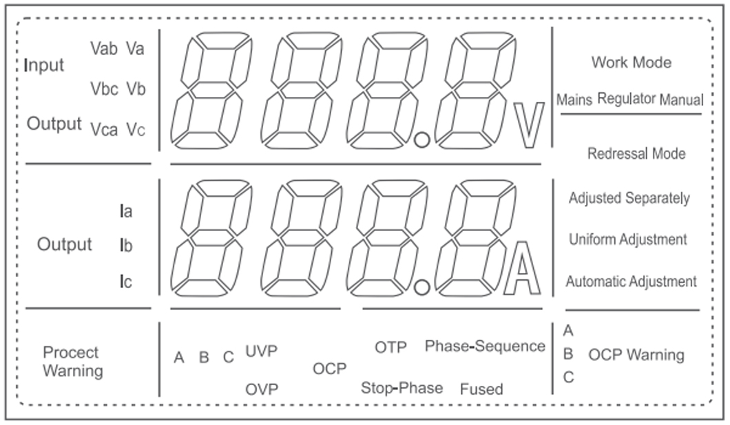
The display window
In the running state, the upper display window is a voltage display window, and the input voltages Va, Vb, Vc, Vab, Vbc, Vca and the
output voltages Va, Vb, Vc, Vab, Vbc, Vca are displayed, and are switched by the voltage switching key. The voltage displayed by the
primary voltage switching button is switched once at Va, Vb, Vc, Vab, Vbc, and Vca, and the voltage displayed after the voltage switching
button is continuously connected for 3 seconds is switched between the input voltage and the output voltage. The lower display window
shows the output currents Ia, Ib, and Ic, which are switched by the current switching key. The panel diagram is as follows:
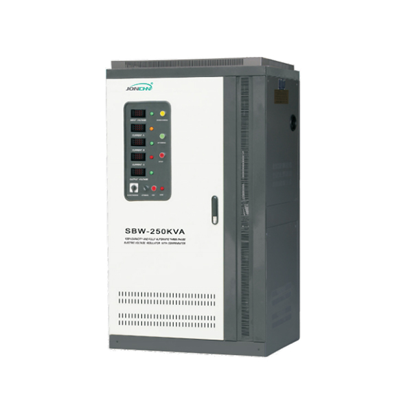
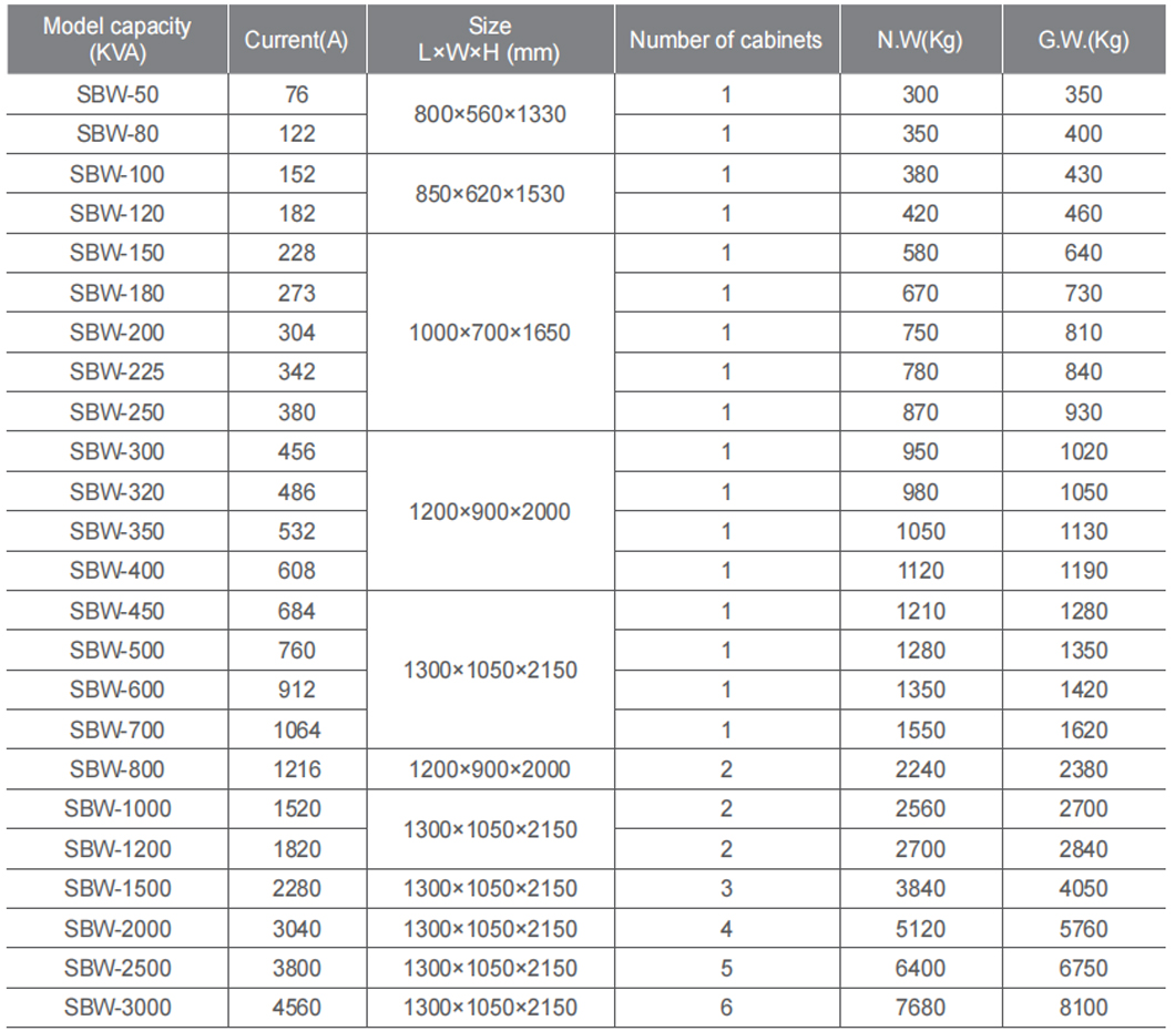
Product features
The SBW series is a three-phase regulated regulator. The voltages of the three phases A, B and C are synchronously adjusted by a
servo motor, and the sampling voltage is the average value of the three-phase voltages of the regulators A, B and C.
The SBW-F series is a three-phase split regulator. The voltages of each phase of A, B and C are independently adjusted by a servo
motor, so there are three independent servo drive mechanisms, and the sampling voltage is the phase voltage of each phase of the
output of the regulator. This model is suitable for grid or load imbalance situations where the input voltage is extremely unbalanced
or for precision equipment.
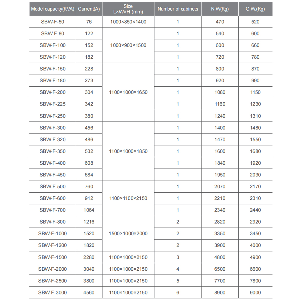
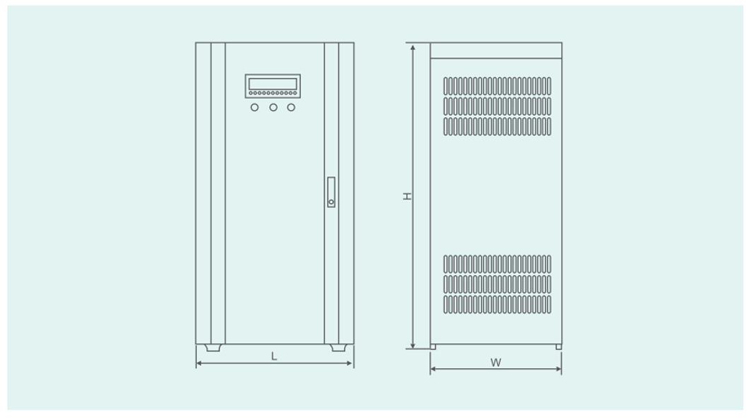
Note 1: Dimensions, weights, etc. are for reference only and are subject to change without notice.
Note 2: All the above products have bypass and no self-start.
Note 3: If the customer has self-starting requirements, please contact the manufacturer.
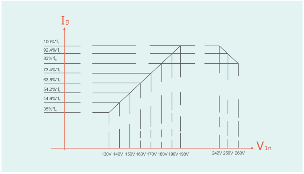
The relative graph of current and input voltage
Inverse time overcurrent protection characteristic, the relationship between output current and protection hysteresis time:
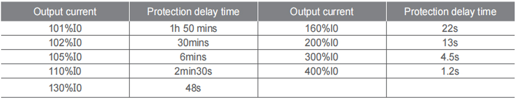
The relative graph of current and protection delay time.
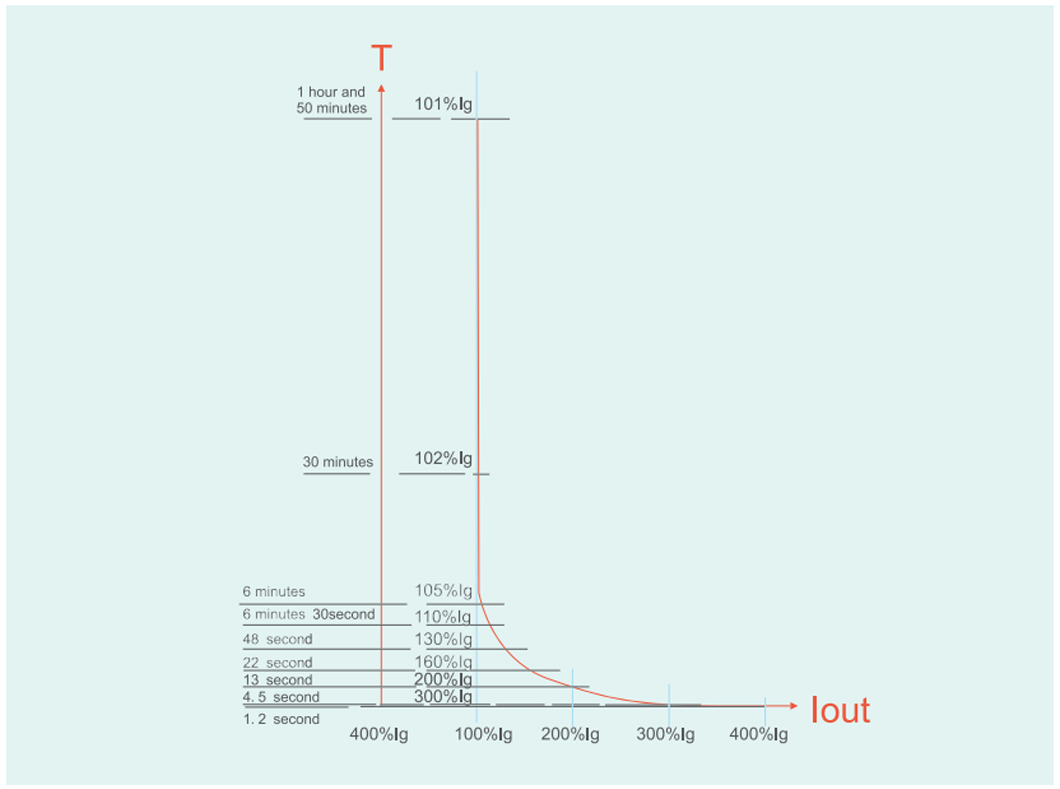
T is the protection delay time, Iout is the output current, and Ig is the current overcurrent protection value.
Fault inquiry
In the running state, press the increase button and decrease button for more than 3 seconds to enter the fault query. The fault code
is: 0 means no fault, 1 means overvoltage and "overvoltage" display, 2 means undervoltage and "undervoltage" display, 3 means
overcurrent and "overcurrent" display. 5 indicates the phase sequence simultaneous "phase sequence" display. 6 indicates the absence
of the same "phase loss" display. After entering the fault query, the above display window displays b1, indicating the most recent fault.
The following display window displays the most recent code, and the protection display window displays the most recent fault type. After
pressing the setting button again, the above display window displays b2, the lower display window shows the code of the last previous
fault, and the protection display window shows the last previous fault type. After pressing the setting button again, the voltage display
window displays b3. The lower display window displays the code of the last two previous faults. The protection display window displays
the last two previous fault types. Press the Set button again to enter the running state.